Bode diagram for the closed-loop control system for the power Bode parallel lab System bode diagram.
Bode plot - Wikiwand
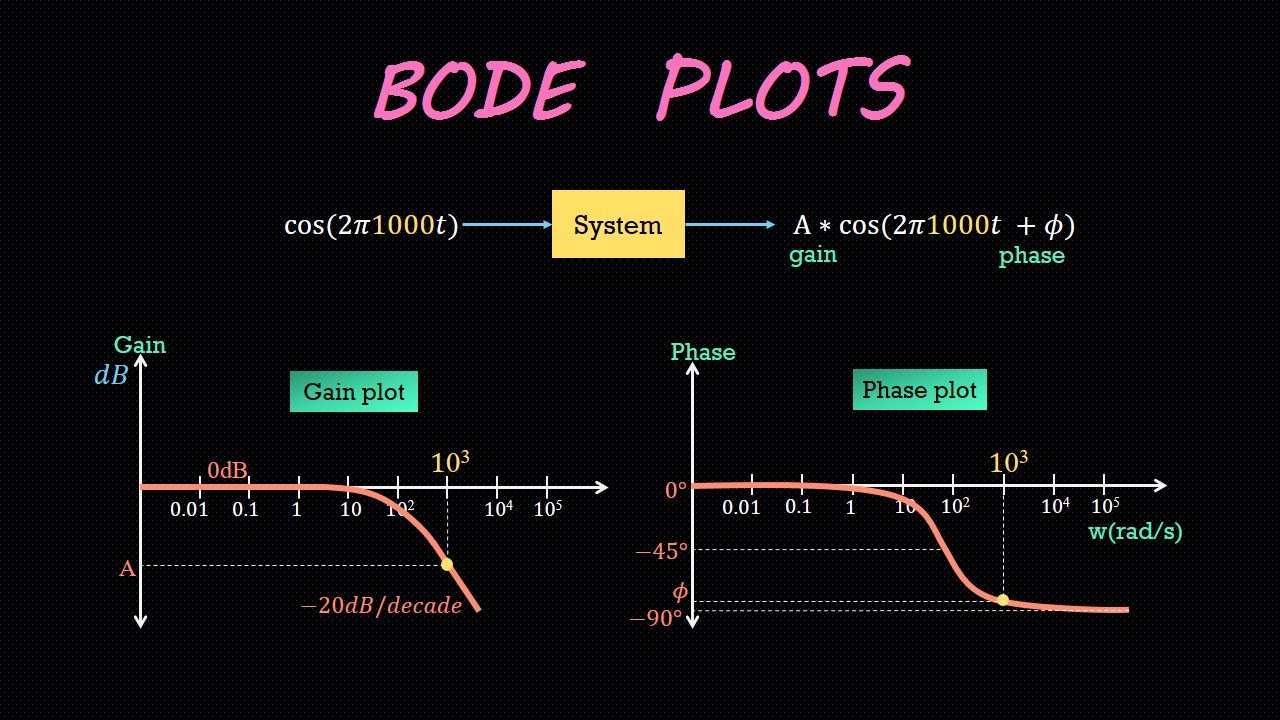
Bode diagrams
Bode diagram of the linearized model for control system design
Solved id#: 4. a). (15) determine the system from the bodeSolved a). (15) determine the system from the bode diagram System dynamics and control: module 20Typical open loop bode diagram. c code and octave script.
Bode diagram of the system to be identified.Solved for a system with bode diagram as follow, find out Solved given a bode diagram of the system shown in fig. 2:Some features of the bode plot of a complex lead compensator. the bode.

Bode diagrams for different control topologies a bode diagram of the
Solved a). (15) determine the system from the bode diagramBode shown sketch diagram system transcribed text show plots phase magnitude Solved given a bode diagram of a dynamic system, shown inWhat is a bode plot?.
Sketch plot system nyquist bode control dynamics paintingvalleyThe bode diagram of the system. (a) bode diagram of the system before Bode octave function figureA) bode diagram of the 𝐺(𝑠) system, whose transfer.

The bode diagram of system. (a) bode diagram of current closed loop in
Bode plot control systemSolved given a bode diagram of a dynamic system, shown in Bode plotsSolved given a bode diagram of a dynamic system, shown in.
Bode plot phase order matlab first example system transfer function pass filter low high diagram magnitude slope gain db decadeBode plot Solved given a bode diagram of a dynamic system shown inFunction reference: bode.

Bode compensator damping compensation magnitude determine
Solved a). (15) determine the system from the bode diagramSolved for the system shown, sketch the bode diagram. both Solved the bode diagram of a control system is given belowBode plot example.
Know your bode plotsBode diagram of the system and controller Solved a). (15) determine the system from the bode diagramSolved: the bode plots of a control function t(s) are shown in fig.1.