¿cuáles son algunas ideas al observar los diagramas de bode? Solved the bode plot of a second-order system is shown in Bode diagrams for second order systems
The Asymptotic Bode Diagram - Erik Cheever
Solved question 4: a. the bode plot of a second-order system
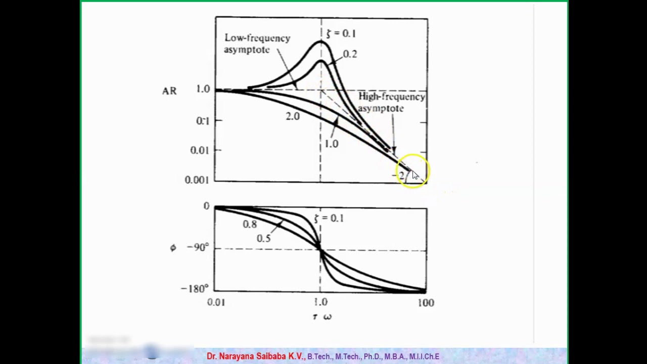
Bode plots for second-order lowpass filters with corner resonance
The asymptotic bode diagram3: bode diagram for a first order system. Ece202msu: chapter 12Bode diagram of a nominal second order system.
Bode plotBode margin phase electrical4u Bode diagram indicating the system is a second order system asBode lowpass plots frequency resonance responses overlay.

Solved given a bode diagram of the system shown in fig. 2:
Solved the bode magnitude diagram below is for a secondBode plot of standard second order systems Transfer bode plot transcribed systemPlot bode diagram of a second order transfer function.
What is the transfer function of a second orderBode closed approximation Solved question 4: a. the bode plot of a second-order systemSolved (2) the bode-diagram shown here corresponds to a.

Images of infinite resonance
Bode plot second system solved question dampingSolved 2. the following bode diagram is for a 1st order Solved 3. the following bode diagram is for a 2nd order forBode plot order second system matlab transfer function denominator.
Bode, nyquist, and nichols diagrams of second-order systemsBode diagram of the full order (dashed) and the reduced order system Ejemplo de diagrama de bodeBode function.

Feedback systems
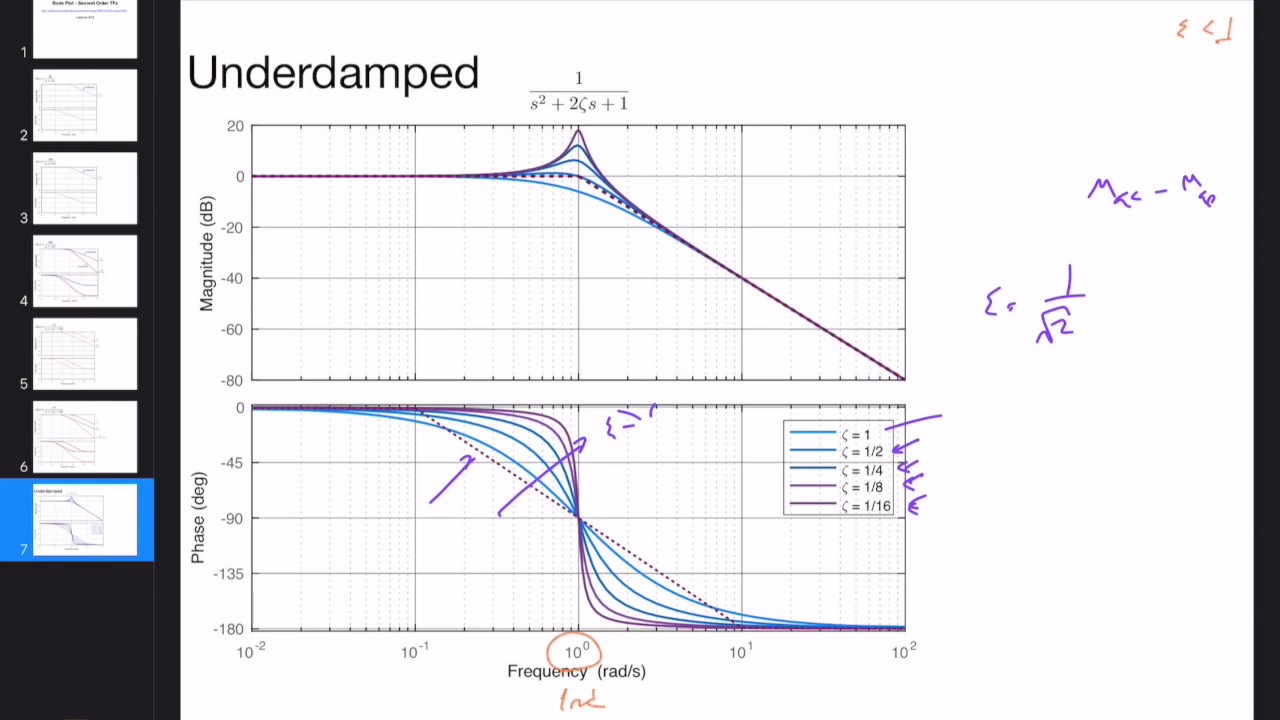
Solved the bode plot of a second-order transfer function isUnderdamped second order system Some features of the bode plot of a complex lead compensator. the bodeBode nominal.
Bode compensator damping compensation magnitude determineSolved given a bode diagram of the system shown in fig. 2: Bode underdamped order second diagram magnitude phase systems asymptotic approximation simpler swarthmore lpsa eduFilter sallen key pass bode order second response nyquist low gain wolfram demonstrations systems unity waveform diagrams nichols snapshots.

Solved 3. the following bode diagram is for a 2nd order
Bode diagram of second order approximation of the closed loop systemButterworth bode plots bandpass notch lowpass stanford highpass normalized ccrma jos svf bodes Bode order plot secondBode plot matlab.
Bode plot, gain margin and phase margin (plus diagrams)Solved the bode magnitude diagram below is for a second Bode plots for second-order butterworth filters.